The ECN network supports three levels of redundancy, which are defined as follows:
|
Redundancy Level
|
Failed Part
|
Impact of Failure
|
|
Level 1
|
No backup
|
|
Level 2
|
There is no single point of failure in the network. Once a failure occurs, certain functions cannot be performed.
|
|
Failure of CS
|
The network can be restored, but the ED connected to the failed CS cannot communicate with other ED
|
|
Link failure between CS
|
The network can be restored
|
|
Link failure between CS and ED
|
The ED with the failed links cannot communicate with other ED
|
|
Level 3
|
When there is a single point of failure, all functions are normally available
When there are two points of failure, the functions are available as much as possible
|
|
Failure of CS
|
The network can be restored, and the ED connected to the failed CS can communicate normally
|
|
Link failure between CS
|
The network can be restored
|
|
Link failure between CS and ED
|
The ED with the failed links can still communicate
|
Different network topologies correspond to different redundancy levels:
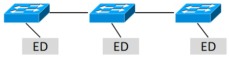
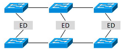
• Level 1:Linear topology
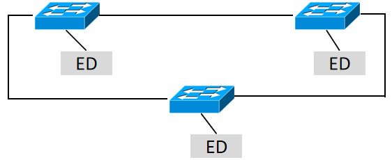
• Level 2:Ring topology
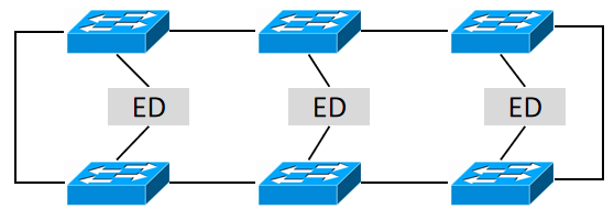
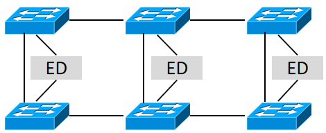
• Level 3:Dual Home parallel network
• Level 3:Dual Home ring network
• Level 3:Dual Home ladder network
ED (Dual home)
ED Dual home means that the ED has two independent interfaces connected to the network. If one link fails, the other can continue to communicate. The following are two examples of Dual home implementations:
• Both interfaces work simultaneously: Packets are sent independently from the two ports respectively. The receiving device processes the packet received first and discards the packet received later. Therefore, the sequence number in the packet may be used. (In practical applications, the two ports of the ED may be configured with different destination IPs and ComId, and the two ports independently publish PD. In this case, the receiving device will not discard the packet received later based on the sequence number in the packet.)
• One interface work: Under normal circumstances, only one link is in operation. When this link fails, it switches to the other backup link. If this method is used, there will be a service interruption during the link switching.