1. Overview
Synchronous HDLC serial communication, different from ordinary asynchronous communication, the clock signal plays an important role, only the sender and receiver use the same clock, can achieve highly reliable data transmission.
2. RS-232/422 Full-Duplex Mode
2.1 Comparison between synchronous and asynchronous
In this paper, RS-232 is used to explain. The principle of RS-422 is the same, but the signal becomes a differential line and its number doubles.
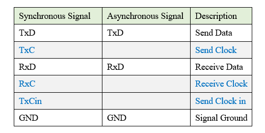
It can be seen from the following table that compared with the asynchronous signal, the synchronous serial port signal increases the clock signals such as TxC, RxC, and TxCin.
2.2 Internal clock sending
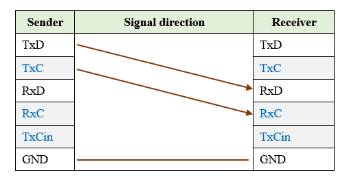
The internal clock sending mode is easier to understand, that is, the sending party generates the sending clock.
In the connection mode shown in the following diagram, the sender generates a clock signal and sends it to the receiver 's RxC. The receiver uses the clock to sample data to ensure the reliability of the data.
2.3 External clock sending mode 1
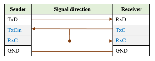
When the receiver is a transmission device, in order to ensure the consistency of the entire transmission link clock, the transmission device, that is, the receiver, generally provides the sending clock.
At this time, the device as the sender must be set to the external clock sending mode (or clock slave mode).
As shown in the following figure, the receiver generates the sending clock TxC, accesses the sender 's TxCin pin, and the sender uses this as the sending clock.
2.4 External clock sending mode 2
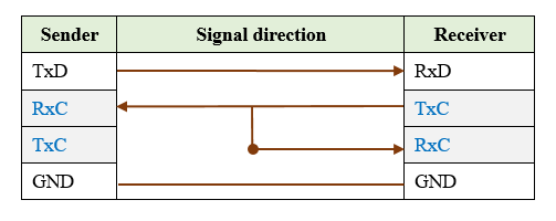
Some HDLC synchronous serial ports do not provide TxCin pins. Generally, external clock can be accessed through RxC pins.
3. RS-485 Half-Duplex Mode
3.1 HDLC synchronous communication based on RS-485 with clock signal
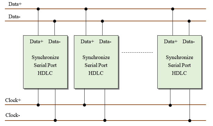
Since HDLC is synchronous communication, a clock signal is necessary to keep the data bits synchronized, so the bus is composed of two pairs of differential lines, namely data bus and clock bus.
When sending, the clock signal and data signal are output at the same time. The node switches to the receiving state when the transmission is completed, and the clock and data stop sending.
3.2 HDLC synchronous communication based on RS-485 without clock signal
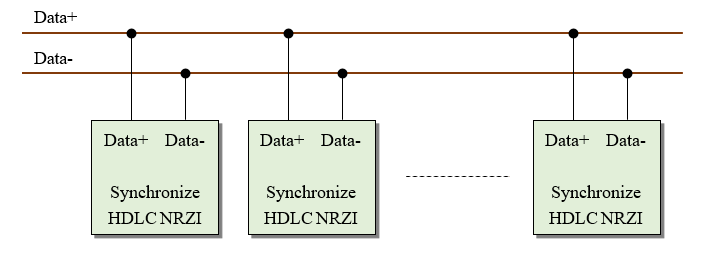
In some HDLC synchronous communication applications, the system can provide only one pair of data differential lines. This requires the data signals to be encoded in a format that carries clock information, such as NRZI, Manchester encoding, etc.
The typical application is the train TCMS application, which uses NRZI coding and a pair of data differential lines as RS-485 bus. Under the condition that all nodes on the bus agree on a same baud rate, the reliability of HDLC communication can be ensured.
