1 Introduction
RS-232 is an interface standard for serial data communication formulated by the Electronic Industries Alliance (EIA) of the United States. The full original number is EIA-RS-232 (abbreviated as 232 or RS232). It is widely used for connecting peripherals to computer serial interfaces.
The RS-232C standard, where EIA (Electronic Industry Association) represents the Electronic Industries Alliance of the United States, RS (Recommended standard) represents the recommended standard, 232 is the identification number, and C represents the third revision of RS232 (in 1969). Before this, there were also RS232B and RS232A.
2 Interface Definition
The full name of RS232 is "Technical Standard for the Serial Binary Data Exchange Interface between Data Terminal Equipment (DTE) and Data Communication Equipment (DCE)". This standard stipulates the use of a DB25 connector with 25 pins, specifies the signal content of each pin of the connector, and also stipulates the voltage levels of various signals. Generally, only three pins, namely 2 (RXD), 3 (TXD), and 7 (GND), are used for the serial port of DB25. With the continuous improvement of equipment, the DB25 pin connector is rarely seen nowadays. It has been replaced by the DB9 interface. The pins used by DB9 have changed compared with those of DB25, and they are 2 (TXD), 3 (RXD), and 5 (GND). Therefore, the RS232 interface is now commonly referred to as DB9.
2.1 Pin Definition of DB9
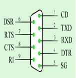
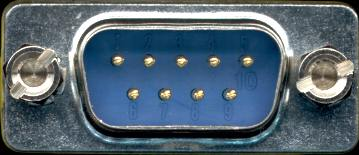
The physical diagram of the male connector of the DB9 interface is shown in the following figure. The first pin is located at the upper left corner, and the ninth pin is at the lower right corner.


Figure 1 Pin Definition and Physical Diagram of DB9
The definitions of each pin of the DB9 are shown in Table 1.
|
Pin
|
Symbol
|
Definition
|
|
1
|
Carrier Detect
|
CD
|
|
2
|
Receive Data
|
RXD
|
|
3
|
Transmit Data
|
TXD
|
|
4
|
Data Terminal Ready
|
DTR
|
|
5
|
Signal Ground
|
SG
|
|
6
|
Data Set Ready
|
DSR
|
|
7
|
Request To Send
|
RTS
|
|
8
|
Clear To Send
|
CTS
|
|
9
|
Ring Indicator
|
RI
|
Table 1 Pin Definitions of DB9
2.2 Pin Definition of DB25
Figure 2 Pins of the DB25 Interface and Male/Female Interfaces
The pin definitions and physical appearance of the DB25 are shown in Figure 2.
The definitions of each pin of the DB25 are shown in Table 2.
Table 2 Pin Definitions of DB25
|
Pin
|
Symbol
|
Definition
|
|
1
|
Shielded Ground Line
|
FG
|
|
2
|
Transmit Data
|
TXD
|
|
3
|
Receive Data
|
RXD
|
|
4
|
Request To Send
|
RTS
|
|
5
|
Clear To Send
|
CTS
|
|
6
|
Data Set Ready
|
DSR
|
|
7
|
Signal Ground
|
SG
|
|
8
|
Carrier Detect
|
CD
|
|
9
|
Transmit Return
|
|
|
10
|
Undefined
|
|
|
11
|
Data Transmission
|
|
|
12~17
|
Undefined
|
|
|
18
|
Data Reception
|
|
|
19
|
Undefined
|
|
|
20
|
Data Terminal Ready
|
DTR
|
|
21
|
Undefined
|
|
|
22
|
Ring
|
RI
|
|
23
|
Undefined
|
|
|
24
|
Undefined
|
|
|
25
|
Receive Return
|
|
3 Characteristics of RS232
● In fact, among the 25 leads of RS-232-C for the signal content of the interface, many are rarely used. In the communication between a computer and a terminal, generally only 3 to 9 leads are used.
● For the electrical characteristics of the interface, the voltage of any signal line in RS-232-C has a negative logic relationship. That is: logic "1" corresponds to -5 to -15V; logic "0" corresponds to +5 to +15V. The noise tolerance is 2V. That is, it is required that the receiver can recognize a signal as low as +3V as logic "0" and a signal as high as -3V as logic "1".
● Regarding the physical structure of the interface, the RS-232-C interface connector generally uses a 25-pin plug and socket of the DB-25 model. Usually, the plug is at the DCE end and the socket is at the DTE end. For the RS-232-C interface of some devices connected to a PC, since the transmission control signals of the other party are not used, only three interface lines are needed, namely "transmit data", "receive data" and "signal ground". Therefore, a 9-pin plug and socket of DB-9 is adopted, and the transmission line uses shielded twisted pair.
● The length of the transmission cable. According to the RS-232C standard, when the symbol distortion is less than 4%, the length of the transmission cable should be 50 feet. In fact, this 4% symbol distortion is very conservative. In practical applications, about 99% of users work within the range of 10-20% symbol distortion. So in actual use, the maximum distance will be far more than 50 feet. The American DEC company once specified that the allowable symbol distortion is 10% and obtained the experimental results in the attached Table 2. Among them, Cable No. 1 is a shielded cable, with the model DECP.NO.9107723, which contains three pairs of twisted pairs, each pair composed of 22# AWG, and it is covered with a shielding net outside. Cable No. 2 is an unshielded cable. The model is DECP.NO.9105856-04, which is a four-core cable of 22#AWG.
4 Disadvantages of RS232
● The signal level values of the interface are relatively high, which makes it easy to damage the chips of the interface circuit. Also, since it is not compatible with TTL levels, a level conversion circuit is required to connect it with TTL circuits.
● The transmission rate is relatively low. In asynchronous transmission, the baud rate is 20Kbps.
● The interface uses one signal line and one signal return line to form a common-ground transmission mode. This common-ground transmission is prone to common-mode interference, so it has weak anti-noise interference ability.
● The transmission distance is limited. The standard maximum transmission distance is 50 feet, and in practice, it can only be used within about 50 meters.


