1 Introduction
The Electronic Industries Association (EIA) formulated and released the RS-485 standard in 1983. After being revised by the Telecommunications Industry Association (TIA), it was named TIA/EIA-485-A, and is customarily referred to as the RS-485 standard.
The RS-485 standard was developed to make up for the shortcomings of RS-232, such as short communication distance and low transmission rate. The RS-485 standard only specifies the electrical characteristics of the balanced transmitter and receiver, but does not define the connectors, transmission cables, and communication protocols at the application layer.
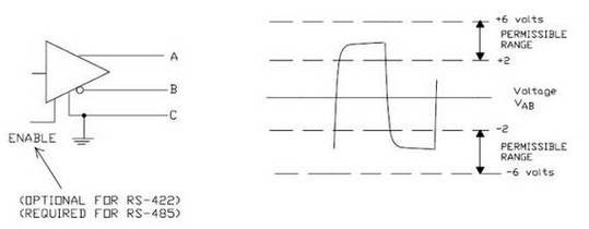
The RS-485 standard is different from RS-232. The data signal adopts the differential transmission mode (Differential Driver Mode), also known as balanced transmission. It uses a pair of twisted-pair wires, defining one wire as A and the other as B, as shown in Figure 1.
RS-485接口

Figure 1 Schematic Diagram of the RS485 Transmitter
Under normal circumstances, the positive level between terminals A and B of the transmitter is between +2V and +6V, representing one logical state; the negative level is between -2V and -6V, representing another logical state. There is also a signal ground C. In RS-485 devices, there is generally an "enable" control signal. The "enable" signal is used to control the disconnection and connection between the transmitter and the transmission line. When the "enable" terminal is in effect, the transmitter is in a high-impedance state, which is called the "third state". It is a third state different from the logical "1" and "0".
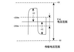
For the receiver, corresponding regulations opposite to those of the transmitter are also made. The receiving and transmitting ends are connected correspondingly with A-A and B-B through balanced twisted-pair wires. When the voltage level between A and B at the receiving end is greater than +200mV, the output is a positive logic level; when it is less than -200mV, the output is a negative logic level. On the receiving balanced line of the receiver, the voltage level range is usually between 200mV and 6V. Refer to Figure 2. The logical 1 (positive logic level) is defined as the state where B > A, and the logical 0 (negative logic level) is defined as the state where A > B. The voltage difference between A and B is not less than 200mV.
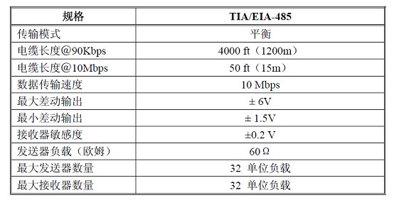
The performance of the TIA/EIA-485 serial communication standard is shown in Table 1:

Table 1 Performance of the TIA/EIA-485 Communication Mode

Figure 2 Schematic Diagram of the RS485 Receiver
The maximum transmission distance of the RS-485 standard is approximately 1219 meters, and the maximum transmission rate is 10Mbps. Usually, the RS-485 network uses balanced twisted-pair wires as the transmission medium. The length of the balanced twisted-pair wires is inversely proportional to the transmission rate. Only when the rate is below 20kbps is it possible to use the longest specified cable length. The highest rate of transmission can only be achieved over a very short distance. Generally speaking, for a 15-meter-long twisted-pair wire, the maximum transmission rate is only 1Mbps.
Note: Not all RS - 485 transceivers can support a communication rate as high as 10Mbps. If the optoelectronic isolation method is adopted, the communication rate is generally limited by the response speed of the optoelectronic isolation device. The RS - 485 network uses a linear topology structure and requires the installation of two terminal matching resistors. The resistance value of these resistors is required to be equal to the characteristic impedance of the transmission cable (usually 120Ω). Terminal matching resistors are not required for short - distance or low - baud - rate data transmission. That is, generally, for distances less than 300 meters and a baud rate of 19200bps, terminal matching resistors are not needed. The terminal matching resistors are installed at the two endpoints of the RS - 485 transmission network and are connected in parallel between the A and B pins. The RS - 485 standard is usually used as a communication platform that is relatively economical, has high noise suppression, a relatively high transmission rate, a long transmission distance, and a wide common - mode range. At the same time, RS - 485 circuits have the advantages of convenient control and low cost.
2 Characteristics of RS-485
Compared with RS232, RS485 has the following characteristics:
● Electrical characteristics of RS-485: Logic "1" is represented by a voltage difference of +(2-6) V between the two wires; logic "0" is represented by a voltage difference of -(2-6) V between the two wires. The interface signal level is lower than that of RS-232-C, which makes it less likely to damage the chips of the interface circuit. Moreover, this level is compatible with the TTL level, facilitating the connection with TTL circuits.
● The maximum data transmission rate of RS-485 is 10Mbps.
● The RS-485 interface adopts a combination of a balanced driver and a differential receiver, which enhances the common-mode rejection capability, that is, it has good anti-noise interference performance.
● The standard maximum transmission distance of the RS-485 interface is 4000 feet, and in fact, it can reach 3000 meters. In addition, the RS-232-C interface only allows one transceiver to be connected on the bus, that is, it has a single-station capability. While the RS-485 interface allows up to 128 transceivers to be connected on the bus, that is, it has a multi-station capability. In this way, users can conveniently establish a device network by using a single RS-485 interface. Due to the good anti-noise interference performance, long transmission distance, and multi-station capability and other above-mentioned advantages of the RS-485 interface, it has become the preferred serial interface. Since the half-duplex network composed of RS485 interfaces generally only requires two connection wires, RS485 interfaces all use shielded twisted-pair wires for transmission. The RS485 interface connector uses a DB-9 9-pin plug and socket. The RS485 interface of the intelligent terminal uses DB-9 (female), and the keyboard interface RS485 connected to the keyboard uses DB-9 (male).
3 Definition of the RS-485 Interface
There is no unified standard for the interface definition of RS-485. Each manufacturer uses the interface they consider appropriate, such as DB9, RJ45, RJ11, etc. Therefore, the definition of the interface pins should be referred to in the specific product instruction manual.


